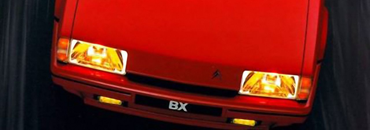
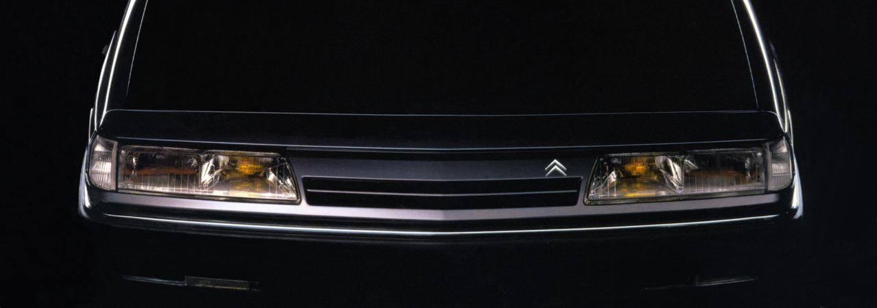
CITROËN BX do-it-yourself

Electrical problems

Electrical measurements

[Picture: A simple digital multimeter]

A rather simple, basic multimeter is enough to check and troubleshoot the electrical parts of the car. Such multimeters can be purchased at hardware or electronics stores. The picture shows a genuine noname multimeter although I saw the very same unit under many brand names and disguises. Noname meters may not be safe if used to measure higher voltages but in the 12 V network of the car there are hardly other risks than blowing some fuses.

They can measure voltage (Volt), current (Amper) and resistance (ohm). Accuracy is not of utmost importance, however, a somewhat more expensive but robust and reliable multimeter pays for itself in the long run.

Multimeters can be either analog or digital: the analog ones have a traditional needle gauge while digital ones—like the one on the picture--a simple LCD display of generally three or four digits. Digital meters are ubiquitous today and they withstand the rugged environment in a car much better; in addition, you don't have to learn how to read the scales.

A very important parameter of every voltmeter is its internal impedance (measured in ohms per volt). Less important if you measure in the conventional parts of the electrical system but if you want to look around near the electronic circuits (like injection or ABS ECUs), a meter with an impedance of 10 MΩ or more is essential. Analog meters are usually much better in this respect: even cheap ones generally have acceptable impedance, with cheap digital meters you have to be careful (for instance, the one on the picture is rather bad as well).

How to use the meter?

You probably have an instruction manual bundled with the meter but in any way, you'll need a battery inside the meter to supply current for resistance measurement and two probes (wires, usually one red and one black) which plug into the sockets on the meter. About the battery and its location you'll have to consult the manual.

The meter has some sort of a selector switch (a rotary one like on the picture or a series of buttons) to select the required mode of operation. Voltage is represented by V or U, current by A or I, resistance by (uppercase Greek omega) or R. DC (or =) and AC (or ≈) are used as modifiers to denote direct and alternate current. Simpler multimeters have numerous settings, as shown on the picture: each area (DCV, ACV, DCA or Ω) has several settings. For instance, in the 20 DCV mode you can measure between zero and 20 V direct current, in the 20 kΩ mode between zero and 20 kohm or 20,000 ohm). More sophisticated meters have only DCV or modes and they select their actual measuring range automatically, informing you of the unit selected on the display.

You will find at least two sockets on the multimeter, one will be marked COM (common), GND (ground) or will show the circuit diagram of the ground, an arrow consisting of three horizontal lines as shown on the picture. The markings will inform you which is the second socket to be used for measuring V, A or Ω.

What to measure?

You can measure practically everything in your car with this simple meter but at all costs avoid the high tension leads in the ignition system (the ignition coil, the distributor and the spark plugs): they operate at very high voltages which could result in a nasty or even lethal electrical shock. The meter is not capable of measuring such high voltages, anyway.

* By measuring resistance you can check whether a wire is broken, a sensor is working or a switch is functional. It is very important to note that while measuring resistance, you have to switch off the current in the circuit (by switching the ignition off or, if this is not enough, by disconnecting the battery). The meter wants to use its own battery to send current into the circuit to be measured and if there is some other current in the circuit, this will falsify the readout completely and can even damage the meter.

Connect the probes to the ground and Ω sockets and select the largest setting of the Ohm mode. If the probes don't touch each other, the meter will show overflow, meaning that the value measured is larger than it can display (the meter on the picture shows a left aligned digit 1, other multimeters will have different ways of displaying this condition—if in doubt, check the manual). In this case, this signals that the resistance between the two probes (as they are not connected) is practically infinitely high. If you touch the two probes together, the circuit will be shorted and the readout drops to zero (or a very small value above zero).

While measuring in practice, you'll look for these two values: overflow or infinity means a broken wire, failing switch or bad grounding contact, while (near) zero an existing and good contact. Connect the two probes to the ends of the cable or connectors of the switch (unless you want to measure an electronic circuit with semiconductors inside, it doesn't make any difference which probe connects to which end) and observe the readout.

* To check the functioning of a circuit, measuring voltage is generally more rewarding than measuring resistance. In this case you have to switch the circuit on. Follow the flow of current on the circuit diagram from the battery to the ground and check at each point or connector that you still have the board voltage (12 to 14 V). To accomplish this, connect the probes to the ground and V sockets and select the largest setting of the DC Volt mode (as you can be reasonably safe that there are no hundreds of volts in the car, you can start from the 20 V range or higher). Connect the GND probe to a known good ground (an exposed metal part, bolt or connector) and touch the point to be measured with the other probe while observing the display. If you happen to swap the two probes, the meter will measure all right but will inform you about the reversed polarity by displaying a negative value. As you go along the circuit, you need to find about the same voltage along the path everywhere (a small drop is due to the resistance of the wires and components and is of no consequence but a drop of several volts shows a bad contact). If the readout drops to zero, the fault lies between this point and the last one still with adequate voltage.

* The need to measure current is rare, it mostly helps reveal current leaks that flatten the battery. As the battery is capable of supplying rather high currents which could surpass the capacity of the meter, blow fuses or even burn wires and cause fire, it is best left for experienced people who will know how to measure it themselves...

How to connect wires

When you retrofit items not originally fitted to your car, you often have to tap into wires or make new connections not already present in the electrical circuitry. The best way to do that is by soldering. Although making nice soldered joints requires a little bit of training and experience, it's still far from rocket science. Practice here doesn't mean months or years, much more like five minutes, especially as we're not speaking about soldering delicate semiconductor components on multilayer printed circuit boards but a couple of thick wires...

You'll need a soldering iron. Not necessarily a fancy one with electronic temperature control, actually, the best one for automotive use feeds on lighter fluid. It is small, lightweight and portable. I have a Weller Portasol but many other manufacturers have similar products. An alternative would be a small, simple soldering iron that can be connected to the battery of the car.

You'll also need a solder. The usual ones come in the form of a wire (made of alloy of tin and lead), with a core containing a non-corrosive flux (this can be clearly seen if you cut it). You won't need any extra flux.

Although, with some practice, it is possible to create perfect soldered joints in one go, the easiest and most reliable way, especially in the beginning, is to use a two step process: first, you coat both wires or parts to be connected with a thin layer of solder (this is called tinning), independently from each other, second, you connect them with more solder.

For practicing, use a length of wire as the one used in the car. Remove 1 cm of the insulation from the end of the wire and twist the copper wires slightly with your fingers to make the individual wire strands stay together. Put the copper wire on the flat surface of the tip of the hot soldering iron and apply the solder from the other side. This is very important, you always have to heat from one side and to apply the solder from the other side. Never heat the solder directly, heat the wire and let the heat transferred by it reach the solder. As soon as this happens, the solder will melt and the appropriate amount will be literally sucked in to fill the gap between the wire strands, fusing them together. The tinning will be perfect when the strands are coated with a thin coat of solder. It's not a problem if some of the wire strands can still be seen under the coat, just make sure the solder forms a smooth, shiny surface. You can always re-heat the wire and add a little bit of extra solder if necessary—but always make sure you re-heat it completely, so that all the solder melts and flows again; never accept new globules of solder glued to the aready existing coating. Everything soldered has to be shiny and smooth on the surface, the solder blending together to form a single entity.

If there is excess solder on the wire or the tip of the iron, simply wipe it off using a damp sponge, and start all over again. Soldering iron stands always have a sponge for this purpose but you can use any similar sponge, however, make sure it is real sponge, not something plastic that will melt on the tip of the hot iron. If you don't have one, you can use several layers of wet kitchen paper towels or a damp lint-free cloth (again, not plastic) but always be careful, the iron is hot.

If you do it the way described, it will be easy and practically automatic. Practice tinning stripped wire ends until you are satisfied with the results.

Now, tin two wires and place them flat against each other so that the stripped, tinned parts will lie flat on each other. Rig something to keep the wire in place so that both your hands will be free (a small vice, a pair of pliers on the table, whatever can keep them temporarily). Position them so that you can apply the hot iron to one side, the flat tip of the iron heating both wires at the same time, and apply the solder from the other side again. As soon as both wires become hot, their solder coating will melt together, using up some new solder as well. As soon as this happens, remove both the iron and the solder and leave the wires cool for a second or so (actually, to get an idea of how long it takes for the solder to harden, you can deliberately try to pull the wires apart during your first attempts).

If you did it right, the solder will form a uniform coating over the wires, shiny, smooth. It should enclose both wires on both sides. If you find that it is nice from the side you applied the solder to but the individual wires can still be seen from the other side because there wasn't enough solder there to fill the gap between the wires completely, try swapping sides, heat the other side now and apply the solder to this side. But swapping sides is only for practicing. In real life, you don't have to solder a joint from both sides, it has to be correct for the first try. In your next attempt, let the heated joint consume a little bit more extra solder. Once you get the amount right, it will evenly fill all sides in one go.

Whenever you have to add solder to a joint, always re-heat the whole joint. Adding solder to one side of the joint so that it forms a piggy-back globule will make a bad joint. The rule of thumb is that, after you are finished with soldering, you shouldn't see any boundary or marks between old and new solder. Everything has to be shiny, smooth, in a single blob of solder. In any other case, the joint will be unreliable both mechanically and electrically.

And again, because this is the single most important issue in soldering, one that makes or breaks a connection: either you tin, make a new connection or repair an existing joint, you always have to heat the wire completely and thoroughly, so that all the solder will melt and flow. The easiest and practically foolprof way to achieve this is to apply heat from one side and solder from the other. This ensures that when the solder side will already be hot enough to melt the solder, everything in between will also be hot enough.

But how to connect them?

[Picture: Soldering wires] When you practice, try connecting the wires at different angles, one parallel or perpendicular to the other. If you make a correctly soldered joint, all of those will be sufficient both electrically and mechanically. But we will suggest a slightly different approach that, in addition to providing a very strong mechnical connection, able to withstand all kinds of stress in a vehicle and, at the same time, will form joints that are easy to insulate and will look as if they were intended to be there.

Strip the insulation in the middle of the original wire and remove the insulation from the connecting wire as well, in double length. Tin the original wire and wind the new wire nicely around the exposed copper. Solder it in place the usual way: heat from one side, apply solder from the other side. As soon as the wrapping wire is evenly covered with solder, you're done. Insulate as you please: if the other end of the original wire can be disconnected temporarily, a shrinkwrap tube is the nicest and most reliable solution.

Trouble with the central locking

If you have the original remote control fitted, the passenger's side door lock does not activate the central locking by default: the central unit has only two triggering inputs, so Citroën had to use the second one either for that door or for the remote control.

However, if you really have a problem with the central locking, remove the internal trim of the door in question. Disconnect the 3-pin white connector of the door lock switch and the 2-pin brown connector of the lock motor, treat them with contact cleaner and reconnect. If this doesn't help, check the rods and nylon fasteners connecting the various parts of the lock system (compare to the other door if necessary).

If the lock obeys the central locking only does not activate it, check the lock switch: disconnect the white connector again. The switch contacts pin 3 of the connector to pin 1 when the door is locked and to pin 2 when it is unlocked (or vice versa, this cannot be seen on the wiring diagram. If in doubt, check on the other door which is correctly functioning). If everything is functional so far, go to the central control unit beneath the center (handbrake) console—secured by two bolts, the first in front of the handbrake, beneath a black plastic cover, the second beneath the cubby at the rear end. You'll have to disconnect the window lifter switches, too. The central locking unit is there, a black box with a brown 9-pin connector. The central contacts from both door lock switches (pin 3 of the white connectors in the doors) go to pin 2, the other two contacts are pin 5 and 7 for the left door, pin 6 and 8 for the right one. Check the same as you did at the door switch. If the contacts are OK, you'll have every reason to suspect the central unit.

Retrofitting one-touch electric window

The GTi and some TZ trim level diesels have a four-function window regulator switch on the driver's door: regular up and down while you push the button, plus an automatic up and down to the appropriate end position with a single push of the button). It is easy to retrofit this unit to another model with simpler electric lifters: go to a salvage yard and find a GTi or TZx with this unit fitted. Remove the door trim panel and separate the secondary panel housing the window regulator switches. You'll need the four-function switch (in contrast to the simpler switch, this has a middle section with the two arrows pointing up and down, plus two outer buttons with a circle marking). The wiring harness starting from this switch goes to a relay unit in the door, then from the unit to the white connector near the bottom of the door (near the radio speaker) plus the other wiring harness connecting the other (passenger's side) switch to the brown connector at the bottom. In your car, you have to swap the regulator switch, the wiring harness and fit the relay unit with three small screws (its place is already there). That's all.

Christian ULBRICH confirmed that the same unit can be found in some CXs and can also be used but due to the different layout inside the CX door the cabling is shorter than necessary for the BX, thus a little soldering will be required.

Windscreen washer fluid level

Yes, it would have been more logical to combine the two reservoirs into one: as we generally use the rear window washer much less often than the front one, its reservoir is usually still nearly full when that of the windshield is already empty. You can improve the situation by connecting the two reservoirs together. Drill a hole into the sidewall of the reservoirs near the bottom. Fit a banana jack into this hole (don't forget to use some sealing gasket or silicone sealant before you secure it with a nut). Fit a plastic tube over the jacks in the two reservoir to form two communicating vessels. If possible, use a tube with rigid walls to avoid it being clamped under liquid bottles or any other item stored in the bulkhead cavity.

As the reservoir capacity will be practically doubled, it would be a good idea to add a level warning as well. National Semiconductors manufactures a specialized integrated circuit (LM 1830) designed for fluid detection systems.

[Diagram: Low Level Warning Circuit]

This circuit can be used to measure the level of conductive fluids. Chemically pure water is not conductive but tap water (especially if mixed with windshield cleaning fluid) is. It is recommended to use a LED as indicator, in this case there is no need for any additional part (using a bulb would require an additional capacitor between pin 9 and the ground).

In most cases you will be able to find a warning symbol on your instrument panel which is not actually used (manual choke, ABS or engine malfunction warning, catalytic converter warning; mostly in the corners of the tachometer). If everything else is used up, you can still think about the front brake pads warning lamp—after a few years this warning is not too reliable anyway, so you might decide to use it for another purpose. Although, as mentioned before, you could use a standard bulb, too, the best solution is to solder a white (uncolored) LED into the bulb holder. As the LED is sensitive to polarity, you will have to note the way you place the bulb holder into the instrument panel.

You will also need a probe in the reservoir. The easiest solution is to use a simple jack phono plug. Use a plastic tube with the appropriate diameter, glue the phono plug into its end using a silicon sealant. Fix the probe into a hole drilled on the top of the reservoir so that its tip reaches down to the level required. Once the fluid level drops below the tip of the probe, it no longer connects the two connectors of the probe and the integrated circuit lights up the indicator attached.

The rest of the circuit can be housed in a small plastic box and placed either at the end of the probe tube on top of the reservoir or fixed to the bulkhead cavity wall somewhere behind the reservoir. The wiring can be routed together with the wiring harness of the washer pumps crossing the bulkhead into the cabin. The circuit should be fed from a 12 V switched by the ignition key so that it will remain silent when the car is not running—or better yet, from the wire feeding the washer pump: then it will only light up when you try to use the washer.

GSM/DCS mobile phones

All phones have hands-free kits and the dealers are ready to install them but, most often than not, they are not really motivated to keep the original looks of the interior untouched.

It's less important for more modern, Bluetooth phones and kits where there has to be no direct contact, the phone can be put anywhere, even left in your pocket or purse, but with more traditional kits, the most delicate question is the phone holder. It surely is a matter of taste but, for instance, I'd hate to have the holder somewhere on the dashboard where nearly all installation workshops put it. It also depends on your phoning habits: if you use it very often and it's you who places the calls most of the time, it is important to have it in your sight to avoid any danger of accident while you are operating the phone.

However, I found it much prettier to have it on the center console behind the handbrake lever. If you have rear electric windows fitted, the operating switches are located at the end of the console on both sides. In addition, there are many openings there covered by dummy panels. You could, for instance, relocate the two rear window switches to the two corner positions, one behind the other, on the left side of the console. Then you have a clear area above the remaining three dummy panels where you can fit the phone holder. Depending on its size it might make using the small compartment behind the ground clearance lever rather difficult. So, your phone will lie one its back between the front seats and although this is a less advantageous place to operate it while driving, it is also less intrusive.

The rest of the system is easier. The microphone can go either to the driver's side A-pillar, or better yet, to the ceiling lamp—in this second case, both you and your passenger can speak directly into it. Remove the sun shield and the passenger side A-pillar trim panel (you can pull it out after sliding it carefully upwards). Fit the small microphone to the frame of the ceiling lamp on your side (the kits ususally contain a double-sided adhesive or Velcro tape to secure the microphone in place with). The wiring can disappear behind the ceiling carpet through the small circular cover of the roof antenna of the stereo and then travel together with that antenna cable down between the glovebox and the side wall of the car.

In some hands-free kits the speaker unit is separate from the main control unit. The best place I could find for the speaker is behind the upper glovebox. As you remove it (two screws at the bottom and four plugs in the side walls), you will spot the air cooling-heating rectangular tube behind the glovebox opening going its way to the side vent. The speaker unit can sit on this plastic tube, secured in place by two or three nylon ties (like the ones used to keep a wiring harness together). The two speaker grilles in the dashboard are not recommended: put a nice pair of tweeters driven by your radio there instead...

Different phones have different control units. I have a Nokia which is rather small and flat. As the upper glovebox is removed, you can see some room on the left (assuming left-hand drive) of the upper glovebox. But you could also place the unit on top of the mentioned vent tube, side by side with the speaker unit (or these two might be actually in one unit in some hands-free kits) or attach it to the car side wall in the passenger side footwell.

The only remaining item is the antenna. You can drill another hole on the roof to put your antenna there but it works just as well if you hide it somewhere—at least this is my experience. I finally found two feasible places: either inside the cabin, also behind the upper glovebox. If you buy an antenna with a magnetized base, you can simply let is snap to the side wall so that the antenna itself is located horizontally, just in front of the speaker unit. Or, you can fit it in the bulkhead cavity behind the engine, behind the washer reservoir, beneath the plastic grille the wiper arm is coming through; secured in the same manner, using its magnetized foot to snap it to the steel side wall. In the second case you can take the same route with its cable which the washer pump wiring and the windshield wiper motor use.

In theory, the antenna should be vertical and it should be not inside the cabin which acts as a Faraday cage. In practice, however, I found no difference at all (and I tried with a Nokia phone with the net monitor switched on; in this mode of operation it can display the measured field strength of the radio signals).

Modified windshield wiper

When it is not raining too hard, the water wiped to the left side of the window, comes back up because of the wind and hinders the view through the windshield. Other cars having only one wiper arm—namely Mercedes—have the resting position on the left side of the windshield. This can be achieved on the BX easily: remove the wiper arm and the plastic cover above the wiper and blower motors. Rotate the small iron arm of the wiper rod mechanism by 180° so that the spindle of the arm would rotate in the opposite position. Replace the cover and re-fit the wiper arm, this time to the left of the windshield.

IJsbrant SMITT

Which wiper blade to buy?

I had nothing but bad experience with Bosch wiper blades, be it revolutionary, twin, aerodynamic, whatever. I stick with Champion and Valeo. But one word of caution: when it starts to streak, never rush to buy a new one. Get some alcohol and kitchen paper towel (it's better than Kleenex). Pour some alcohol on the towel, pinch it between your fingernails and literally scrape the blade edge, but hard. Dirt can stick to it with great force. You do this twice or thrice and lo and behold, you blade will probably return to its new condition immediately.

Webmaster:
Gábor DEÁK JAHN.
Visitors: 232,315
Page hits: 599,486
Since: June 5, 2003